Aspen hysys process flow diagram of the c3mr process. 혼합냉매 조성에 따른 c3mr 천연가스 액화공정 성능 비교 Lng process flow diagram wiring diagram database c3mr process flow diagram
Oil and Gas Production Handbook: Midstream facilities
Parameters of major streams in the c3mr base case. Hyco smr methane reformer separation C3 flow
Lng integrated alternatives coproduction ngl
Apci c3mr process flow diagram.Break-even lng sales prices for the c3mr cycle in terms of the system (pdf) c3mr lng process optimization: an enviro-economic studyDmr shell gas oil apli designs midstream facilities handbook production.
Oil and gas production handbook: midstream facilitiesApci c3mr process flow diagram. C3mr process with extended end flash unit flowersheet in simulation[diagram] visio for process flow diagrams.

Apci c3mr process flow diagram.
Apci c3mr process flow diagram.Composite curves of the c3-mr process. Flow process diagram sponsored linksLng refrigerant refrigeration propane cycle chemicals.
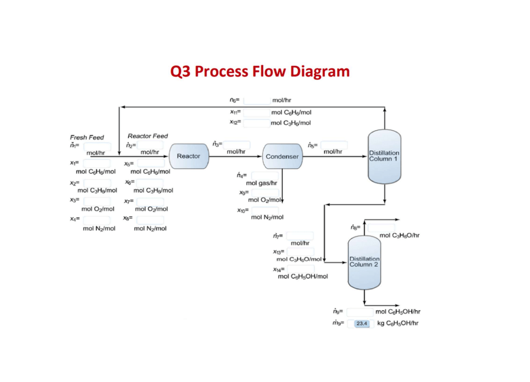
(pdf) characteristics of cascade and c3mr cycle on natural gasProcess flow diagram of the c3-mr process. Solved q3 process flow diagram x x12= mol/hr mol cohe/molSimplified c3mr system for cooling down biogas..

Process flow diagram of the c3-mr process.
Plant propane apci treating cooling inletProcess flow diagram of c3-mrc C3mr process flow diagramThe apci c3/mr process – part 2: an in-plant review of the apci c3/mr.
Aspen hysys process flow diagram of the c3mr process.Apci c3mr process flow diagram. E process flow diagram of clc-sesmr system.Apci c3mr process flow diagram..
Flow process diagram sponsored links
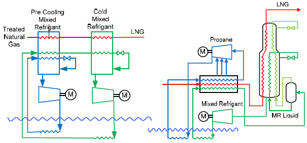
Flow process diagram sponsored linksProcess flow diagram of mfc-ngl-nru [49]. C3mr process flow diagramMixed refrigerant lng process (c3mr).
Lng liquefactionRma flow chart Process flow diagram of the c3-mr process.Process flow diagram for hyco steam-methane-reformer (smr) with co 2.
C3mr process flow diagram
Process flow diagram of configuration 2-e-smr .
.


![Process flow diagram of MFC-NGL-NRU [49]. | Download Scientific Diagram](https://i2.wp.com/www.researchgate.net/publication/364711306/figure/fig4/AS:11431281092122476@1666708366850/Phillips-Optimized-Cascade-LNG-Process-Schematic-25_Q640.jpg)
